
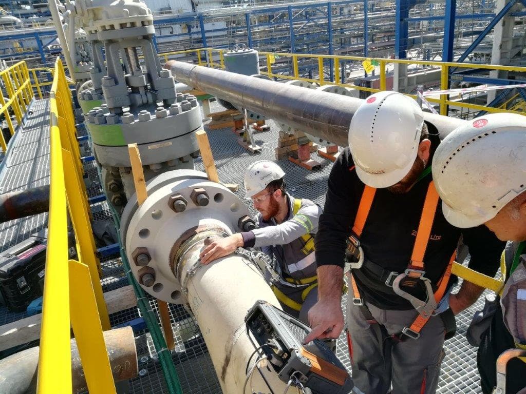
Non-Destructive Testing (NDT)
Radiographic Testing
A method in which X-rays or gamma rays are used to image internal voids, thickness and density variations of a material on a radiation-sensitive film.
Radiographic Testing (RT) is a non-destructive testing method based on passing short-wavelength, high-energy ionising radiation — X-rays or gamma rays — through a material so that a two-dimensional shadow image is formed on a detector (film or digital sensor) placed on the opposite side. As the radiation travels through the material it is absorbed (attenuated) to different degrees depending on the thickness, density and atomic number of the region it passes through. Where a discontinuity such as porosity, slag, a crack or lack of fusion is present, less material is available to absorb the radiation; more radiation therefore reaches the detector and the area appears as a darker (higher-density) mark on the film. In this way the internal structure of the part is imaged without cutting it open.
In practice the radiation source is placed on one surface of the part and the detector on the opposite surface, and the radiation is transmitted through the material for the duration of the exposure. X-ray sources are electrically powered tubes whose energy (kV) and current (mA) can be adjusted for different thicknesses; radiation is produced only while the equipment is energised. Gamma-ray sources, on the other hand, are radioactive isotopes such as Ir-192, Se-75 or Co-60; requiring no electrical supply, they are advantageous in field work and confined spaces, but because they emit radiation continuously they are stored in shielded projector containers. To objectively assure image quality, an image quality indicator (IQI/penetrameter; wire type or hole type) defined in the standards is placed on the part for every exposure, and the finest wire or smallest hole visible on the film demonstrates the sensitivity achieved.
In conventional film radiography the exposed film is processed in a darkroom; the optical density (degree of darkening) of the resulting radiograph is measured with a densitometer and must lie within the range required by the standards. Today, computed radiography (CR) using reusable phosphor imaging plates and digital radiography (DR) using direct digital detector arrays are also widely applied instead of film; these shorten exposure times, eliminate the need for chemical processing and allow the image to be archived and processed digitally (contrast/brightness adjustment, measurement). Correct selection of the technique requires the exposure arrangement (SFD, geometry) to be planned according to material thickness, geometric magnification, source-to-film distance, source size and the permissible unsharpness (geometric sharpness) limits.
Radiographic testing is most often preferred for the volumetric examination of welded joints, because it reveals internal discontinuities such as porosity, slag inclusions, lack of penetration (root defects), incomplete fusion and transverse or longitudinal cracks as a permanent, visual record. Planar discontinuities oriented perpendicular to the beam direction (certain cracks, for example) can be difficult to detect if they lie parallel to the path followed by the radiation; for this reason the method is often evaluated together with ultrasonic testing where the risk of cracking is high. Pipeline welds, pressure vessels, boilers and piping systems, steel structures and castings are typical fields of application. A distinct advantage of the method is that the result is preserved as a physical or digital document (the radiograph) that is independent of the operator and can be re-examined by third parties.
During evaluation the radiograph is examined on an illuminated viewing screen (film viewer) or a calibrated monitor; the type, size and location of the detected discontinuities are determined and compared with the limits of the applicable acceptance standard (fabrication code or contract) to reach an accept/reject decision. The report covers the technique and source used, the IQI sensitivity, the film density, the scope of examination, the findings and the evaluation against the acceptance criteria. TÜV AUSTRIA SILA KALİTE performs radiographic testing as an inspection body accredited to TS EN ISO/IEC 17020, in conformity with the relevant examination and acceptance standards, and documents the results in a traceable inspection report.
Method
The application begins with a preliminary check of the surface condition of the part and the weld to be examined, and with the selection of a suitable technique (X-ray/gamma; film/CR/DR) and exposure geometry (source-to-film distance, exposure layout) according to material type and thickness; the energy/current or isotope activity and the exposure time are then set for the thickness, and an image quality indicator (IQI/penetrameter) together with lead identification and location markers is placed on the part. The exposure is carried out under radiation safety measures (controlled area, dosimetry, warning signage); in the film technique the radiograph is processed and its optical density verified with a densitometer, while in digital techniques the image is scanned/recorded and processed. The resulting image is examined on an appropriately illuminated viewer, discontinuities are characterised and sized, and an accept/reject decision is made by comparison with the limits of the applicable acceptance standard; finally, a traceable inspection report covering the technical parameters, IQI sensitivity, findings and evaluation is issued.
Applications
- Volumetric examination of welded joints (butt and fillet welds)
- Weld seams in pipelines and process piping systems
- Welds in pressure vessels, boilers and reactors
- Steel structures and structural steel connections
- Internal voids, porosity and shrinkage defects in castings
- Refinery, petrochemical and power plant equipment
- Weld seams in ships and offshore structures
- Internal discontinuity control of forged and machined components
Frequently asked questions
Related services
Ultrasonic Testing
A non-destructive testing method that determines the location, size and type of discontinuities by making use of the reflections of high-frequency sound waves within the material.
TÜRKAK 17020 · AB-0120-MView detailsMagnetic Particle Testing
A method based on the principle of inducing a magnetic field in the test piece, used to detect surface defects in ferromagnetic materials.
TÜRKAK 17020 · AB-0120-MView detailsPenetrant Testing
The most widely used non-destructive testing method, in which surface-breaking defects are detected with a visible or fluorescent dye solution.
TÜRKAK 17020 · AB-0120-MView detailsVisual Testing
The oldest and most widely used NDT method, in which imperfections and discontinuities on the material surface are examined with the naked eye or with auxiliary equipment.
TÜRKAK 17020 · AB-0120-MView detailsGet a quote for your project
Receive a fast, GDPR/KVKK-compliant response for the inspection or certification service you need.