
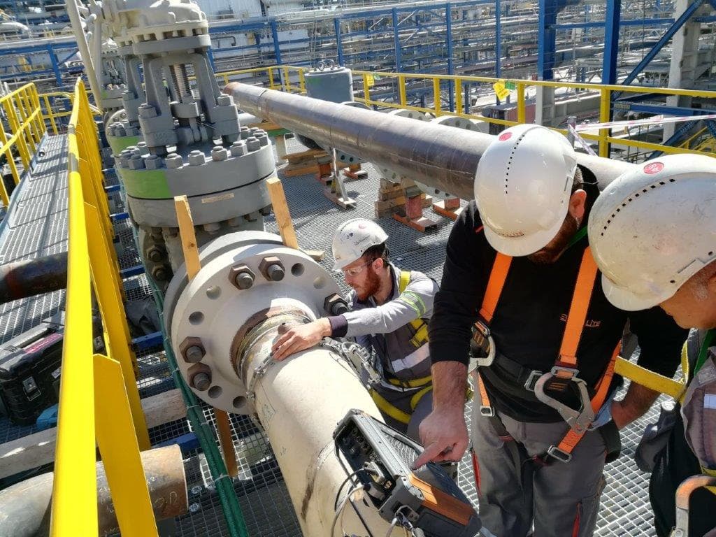
Non-Destructive Testing (NDT)
Leak and Pressure Testing
A test method used to detect defects likely to occur in tank bottom plates and in their butt and fillet welds.
Leak and pressure tests are non-destructive testing applications that evaluate the tightness and structural integrity of a vessel, pipeline or tank shell under a pressure difference created by means of a fluid (liquid or gas). The basic physical principle of the method is that when a pressure difference exists across the two sides of a leak path (a through-wall discontinuity), the fluid migrates from the higher pressure to the lower pressure. This migration produces measurable indications such as bubble formation, pressure drop, or the detection of a tracer gas on the opposite side. Leak Testing (LT) essentially reveals porosity, cracks or weld discontinuities that penetrate the full wall thickness, while pressure testing (hydrostatic or pneumatic) verifies the ability of the equipment to withstand a value above its design pressure and its overall tightness. The two applications are frequently carried out together and are of critical importance at the final acceptance stage after fabrication.
In practice, pressure testing is generally performed in one of two ways. In the hydrostatic test, the vessel is filled with water and raised to a defined multiple of the design pressure (typically 1.25–1.5 times, depending on the code and standard), the pressure is held constant for a specified period, and leaks are sought visually or through pressure recording. In the pneumatic test, compressed air or an inert gas is used; because of the high energy it stores, the pneumatic test carries greater risk and is applied only where the hydrostatic test is not suitable and with strict safety precautions. On the leak testing side, techniques such as the bubble method (application of a foaming solution), the vacuum box, pressure decay and the tracer gas method (helium/leak detector) are selected according to the sensitivity required.
The equipment varies with the technique selected. In pressure tests, calibrated pressure gauges, pressure recorders, safety valves and a filling/draining line are essential; the measuring range is chosen so that the test pressure to be applied falls within the middle third of the range. In the vacuum box technique, a box with a glass bottom face sealed with a gasket is placed over a weld seam coated with foaming solution; when a vacuum is created inside the box, air passing through the leak path produces bubbles in the foam and makes the discontinuity visible. In the tracer gas method, helium leak detectors can identify far smaller leak rates (in the order of mbar·L/s) than the bubble method; the technique is selected according to the size of the smallest leak sought.
The method-specific depth becomes particularly evident in storage tank fabrication. Leak paths that may form in the butt and fillet welds of tank bottom plates are regions that in most cases cannot be pressurised directly; bottom seams are therefore commonly scanned with a vacuum box. Alternatively, a penetrating oil/kerosene may be applied to one face of the seam and the leakage monitored from the other face. Foam/pressure methods are preferred at shell and roof joints, and a hydrostatic filling test on complete tanks. For pressure vessels and process piping, the method is adapted to the vessel geometry, the service fluid and the relevant design code.
Evaluation and reporting are carried out against the acceptance criteria of the applicable test/practice standard. In pressure testing, acceptance is based on the absence of any measurable pressure drop and any visible leakage during the specified holding period; in leak testing, on the permitted leak rate not being exceeded. The report contains the test method and technique, the test pressure and holding time, the type of fluid/tracer gas, the ambient and fluid temperatures, the solution/foam used and equipment calibration data, the location of any indications detected, and the accept/reject decision. This documentation serves both as objective evidence of welding fabrication quality and as assurance of the tightness of the tank or pressure equipment before it is put into service; early detection reduces product loss, environmental contamination and safety risks that could otherwise arise during operation.
Method
The application begins with the selection of the test method and technique (hydrostatic/pneumatic pressure testing, or bubble/vacuum box/tracer gas leak testing, according to the vessel type, the service fluid and the relevant code). The surface is then cleaned, adjacent areas are masked, and the calibration and measuring range of pressure gauges and safety valves are verified; if a tracer gas or foaming solution is to be used, the reference sensitivity is set. During application, the equipment is raised gradually to the test pressure and held for the specified period; in the vacuum box technique, foam is applied over the seam and the box is evacuated for scanning. In evaluation, pressure drop, bubble formation or detector signal is interpreted against the acceptance criterion of the standard; indications are marked with their location and type. Finally, the test parameters, ambient/fluid conditions, equipment calibration data and the accept/reject decision are documented in a report.
Applications
- Bottom, shell and roof weld seams of atmospheric storage tanks
- Fuel and chemical storage tank farms
- Pressure vessels and reactors (post-fabrication acceptance testing)
- Process and power plant piping systems
- Tightness control of heat exchangers and tube bundles
- Boilers and steam systems
- Pipeline and valve installation joints
- Tightness verification in water/wastewater and reservoir systems
Frequently asked questions
Related services
Radiographic Testing
A method in which X-rays or gamma rays are used to image internal voids, thickness and density variations of a material on a radiation-sensitive film.
TÜRKAK 17020 · AB-0120-MView detailsUltrasonic Testing
A non-destructive testing method that determines the location, size and type of discontinuities by making use of the reflections of high-frequency sound waves within the material.
TÜRKAK 17020 · AB-0120-MView detailsMagnetic Particle Testing
A method based on the principle of inducing a magnetic field in the test piece, used to detect surface defects in ferromagnetic materials.
TÜRKAK 17020 · AB-0120-MView detailsPenetrant Testing
The most widely used non-destructive testing method, in which surface-breaking defects are detected with a visible or fluorescent dye solution.
TÜRKAK 17020 · AB-0120-MView detailsGet a quote for your project
Receive a fast, GDPR/KVKK-compliant response for the inspection or certification service you need.