
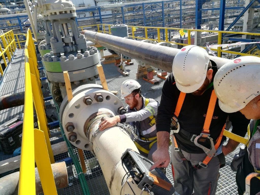
Non-Destructive Testing (NDT)
Eddy Current Testing
An inspection method performed on conductive materials by means of the alternating magnetic field generated by a test coil and the eddy currents it induces in the material.
Eddy Current Testing (ET) is a non-destructive testing method based on the principle of electromagnetic induction, applicable only to materials that are electrically conductive. The method relies on a test coil driven by alternating current, which generates an alternating magnetic field around itself. When this coil is brought close to the surface of a conductive material, closed circular current loops (eddy currents) are induced within the material in accordance with Faraday's law of induction. These induced currents in turn produce their own secondary magnetic field, altering the apparent impedance of the coil (its inductive and resistive components). The presence of a crack, porosity, thickness variation or change in conductivity disturbs the flow path of the eddy currents; the instrument detects this disturbance as a change in coil impedance and thereby reveals the presence of a discontinuity.
The most distinctive feature of the method is that the response to a discontinuity is displayed as a signal vector on the impedance plane. From the screen, the operator obtains information about the size of the flaw from the signal amplitude, and about its depth below the surface from the phase angle. This phase-amplitude discrimination is a consequence of eddy currents concentrating near the surface and decaying exponentially with depth (the skin effect). The depth of penetration is inversely related to the excitation frequency, the conductivity of the material and its magnetic permeability. Low frequencies therefore provide greater depth but lower sensitivity, while high frequencies deliver high-resolution results for discontinuities close to the surface. Frequency selection is the first technical decision that defines the purpose of the inspection.
The coil type used in practice varies with the inspection geometry: encircling coils through which tubes or bars are passed, internal probes (bobbin/IRIS type) for tube inner surfaces, and surface (pancake) probes used for scanning flat surfaces are the principal examples. Absolute probes respond to gradual variations such as conductivity and thickness, while differential probes detect abrupt differences between two adjacent windings and are therefore sensitive to sharp cracks. Modern instruments — with multi-frequency operation, eddy current array probes and mixing functions that suppress the effect of surface coatings — can also evaluate discontinuities beneath paint or oxide layers. In ferromagnetic materials, where fluctuations in magnetic permeability generate noise, a saturation magnet or the remote field technique may be required.
The method takes on different depth depending on the field of application. In heat exchanger and boiler tubes, internal probe scanning rapidly maps corrosion thinning, pitting and cracks; in aerospace, fatigue cracks around rivet holes and aluminium structural members are scanned. In the inspection of weld seams for surface and near-surface cracks, the ability to scan without removing the paint is a significant advantage. The method is also used for purposes other than discontinuity detection, such as material sorting (alloy/hardness mix-up), conductivity measurement, heat treatment verification and the measurement of non-conductive coating thickness.
Eddy current testing offers advantages such as speed, non-contact operation, suitability for automation and single-sided access; its limitations include applicability only to conductive materials, limited penetration depth and a strong dependence of signal interpretation on operator qualification. For this reason, the instrument must be calibrated before inspection on a reference block or standard tube containing representative artificial discontinuities (calibration notches, reference holes). Evaluation is carried out against the acceptance criteria defined by the relevant product standard or contract specification: typically the signal amplitude obtained from the reference artificial flaw is taken as a threshold (rejection level), and indications exceeding it are reported. The report documents the coil type, frequency, calibration standard, scanning coverage, and the location, amplitude and phase data of the indications detected, so that results become traceable and repeatable.
Method
The inspection begins with cleaning the surface of coarse dirt, loose rust and thick layers that would obstruct testing, and with establishing the geometry and material type (conductivity, whether the material is ferromagnetic). A coil type suited to the inspection objective (encircling / internal probe / surface probe) and an excitation frequency are then selected; the instrument is calibrated on a reference block or standard tube containing artificial flaws (notches, side-drilled holes) representative of the target discontinuity, and the threshold/rejection level and phase angle are set. Once calibration is verified, the probe is traversed along the surface or tube at the defined scanning speed and overlap pattern, and impedance plane signals are recorded. The resulting indications are evaluated by comparing their amplitude and phase with the reference signal; the location, size and probable depth of indications exceeding the threshold are determined. At the end of the inspection, the coil/frequency parameters, the calibration standard used, the acceptance criterion and the findings are documented in a traceable inspection report; where necessary, suspect areas are verified with a complementary method (e.g. penetrant or ultrasonic testing).
Applications
- Scanning of heat exchanger, condenser and boiler tubes for corrosion, wall thinning and cracks (internal probe)
- In-line inspection of surface and sub-surface discontinuities in tube and bar production
- Aluminium structural members and fatigue cracks around rivet holes in aerospace and automotive applications
- Inspection of weld seams for surface and sub-surface cracks (without removing the coating)
- Alloy/hardness/heat treatment sorting and material mix-up control through conductivity measurement
- Thickness measurement of non-conductive coatings (paint, anodising)
- Detection of grinding cracks and surface defects in machined parts such as bearings, shafts and gears
- Periodic tube bundle inspections in power plants and refineries
Frequently asked questions
Related services
Positive Material Identification (PMI)
A method in which the characteristic radiation released from atoms under X-ray excitation is measured to characterise the material both quantitatively and qualitatively.
View detailsFerrite Content Measurement
A measurement carried out to guarantee the ferrite content of the final product after welded fabrication of austenitic, duplex and super duplex materials.
View detailsLeak and Pressure Testing
A test method used to detect defects likely to occur in tank bottom plates and in their butt and fillet welds.
View detailsRadiographic Testing
A method in which X-rays or gamma rays are used to image internal voids, thickness and density variations of a material on a radiation-sensitive film.
TÜRKAK 17020 · AB-0120-MView detailsGet a quote for your project
Receive a fast, GDPR/KVKK-compliant response for the inspection or certification service you need.