Advanced Non-Destructive Testing
ToFD (Time of Flight Diffraction)
An ultrasonic method that tests weld seams and critical areas with high accuracy, involves no radiation hazard and provides reliable flaw sizing.
ToFD (Time of Flight Diffraction) is an advanced ultrasonic inspection method that determines the position and size of a discontinuity by measuring the travel time of the diffracted waves emitted from its tips. Unlike conventional pulse-echo techniques, ToFD relies not on the amplitude of the reflected signal but on the time the sound wave takes to travel from the transmitter to the receiver. A transmitter and a receiver probe placed opposite each other on either side of the weld seam (pitch-catch arrangement) send an angled longitudinal beam into the inspection volume. The upper and lower tips of a crack behave like secondary sources that scatter the incoming energy in all directions; the arrival times of these diffracted signals allow the depth below the surface and the vertical extent of the flaw to be calculated directly. Because the method does not depend on amplitude variations, it is largely insensitive to flaw orientation and offers high repeatability in sizing.
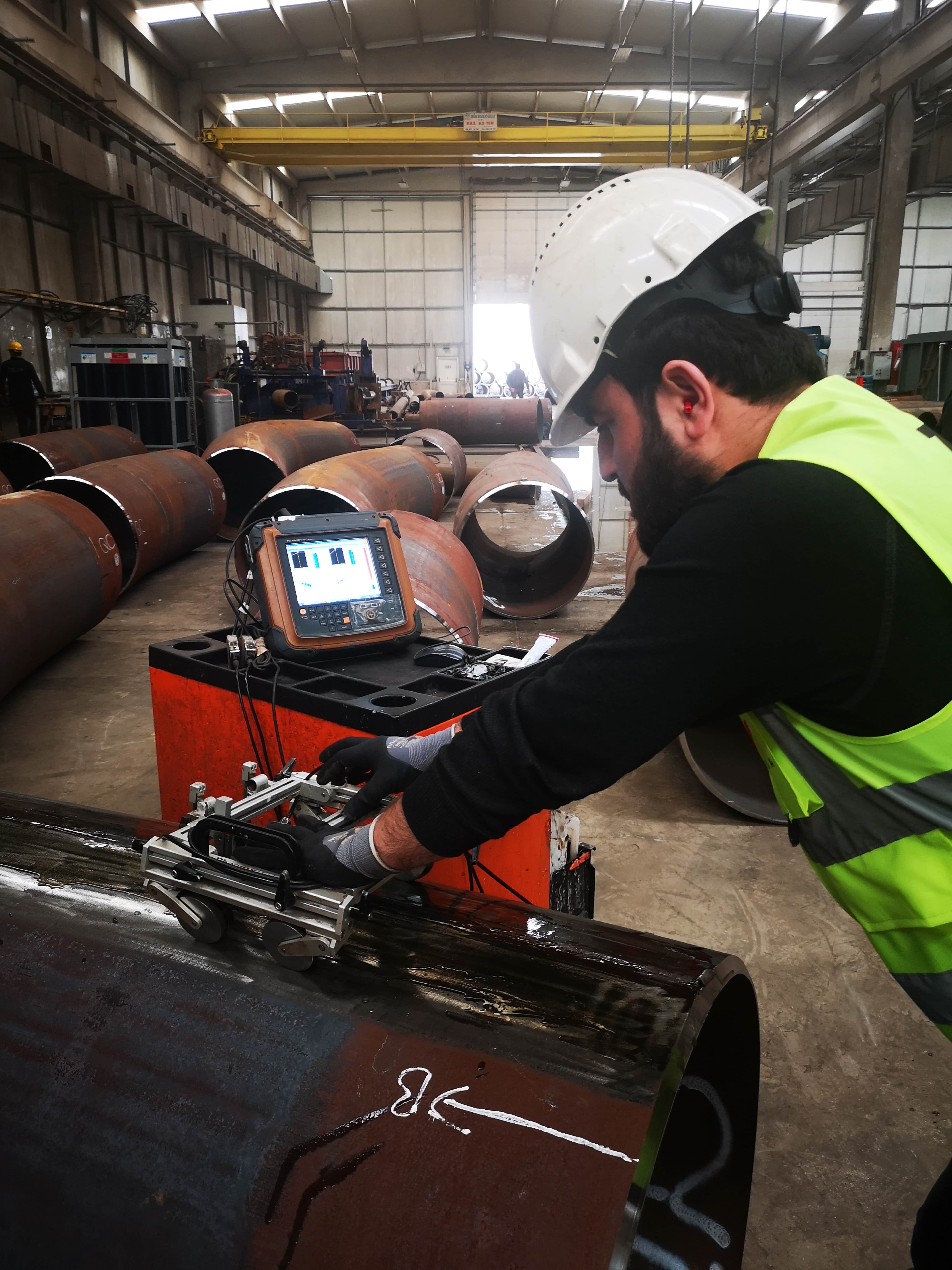
During the inspection the signals recorded by the receiving probe are arranged in a specific time order. The fastest arriving signal is the lateral wave travelling along the surface of the part; the last to arrive is the signal reflected from the backwall. Every diffraction signal appearing between these two references indicates a discontinuity within the material. The phase difference between the upper tip and lower tip signals helps to distinguish whether the signal comes from the top or the bottom edge of the flaw. As the probe pair advances along the weld, the collected A-scan data is arranged side by side to form a grey-scale D-scan image; this image shows the position and depth of flaws along the weld in a single cross-section and provides a permanent, archivable record.
In terms of equipment, ToFD consists of highly damped angled longitudinal wave probes, suitable wedge angles, a digital data acquisition unit and a position encoder that measures the scan position precisely. The probe centre spacing (PCS) is calculated geometrically so that the intersection point of the beams covers the thickness range under examination. In thick components a single scan may not cover the full thickness, so multiple probe pairs or a multi-zone scanning arrangement is used for different depth zones. Before scanning, the system is set on a suitable reference/calibration block in terms of time base and depth.
The greatest strength of the method is the reliable detection and sizing of vertically extending flaws perpendicular to the surface — particularly lack of fusion, cracks and lack of penetration; under suitable conditions the vertical sizing accuracy is in the millimetre range. For this reason it is preferred in the manufacturing inspection of weld seams and especially for the periodic monitoring of crack growth in pressure equipment (non-destructive life assessment). On the other hand there is a dead zone near the surface of the part caused by the lateral wave; this limitation is overcome by scanning from opposite directions, using different PCS values, or applying phased array ultrasonics (PAUT) as a complementary technique. Compared with radiography, the absence of ionising radiation significantly improves site safety and shift continuity.
During evaluation the diffraction signals obtained are measured on the basis of depth and length rather than signal height; flaw dimensions are compared with the acceptance levels of the relevant acceptance standard (for example TS EN ISO 15626) to reach an accept/reject decision. The inspection report records the scan images, the flaw position-depth-size values, the equipment and calibration parameters and the applied standards. TÜV AUSTRIA SILA KALİTE performs ToFD inspection as a TÜRKAK-accredited inspection body under TS EN ISO/IEC 17020, with personnel certified to ISO 9712, in an independent and traceable manner; the customer therefore receives not merely a detection result but a conformity assessment that is defensible both legally and technically.
Method
Application starts with cleaning the weld seam to be inspected and the scanning surface, removing coating, spatter and roughness so that continuous probe contact is possible; the probe angle and the probe centre spacing (PCS) are then determined according to the part thickness, weld geometry and the sound velocity of the material. The instrument is set on a suitable reference/calibration block with respect to the time base, the lateral wave and the backwall position, and the encoder distance calibration is verified. During application the transmitter-receiver probe pair is moved along the scan parallel to the seam with couplant, A-scan data is collected from every position and a grey-scale D-scan image is built up. In evaluation the diffraction signals between the lateral wave and the backwall are interpreted, the depth and vertical extent of the flaw are calculated from the time of flight and compared with the acceptance levels of the relevant standard. Finally the scan images, flaw position and size data, equipment-calibration parameters and applied standards are recorded in a traceable inspection report.
Applications
- Manufacturing and periodic inspection of shell welds in pressure vessels, steam boilers and reactors
- Circumferential/longitudinal butt welds of pipelines and process piping
- Crack monitoring and life assessment on petrochemical, refinery and power plant equipment
- Weld seams of storage tanks and spherical/cylindrical vessels
- Heavy section joints in heavy steel structures and bridge welds
- Wind turbine tower and flange welds
- Volumetric inspection of ship and offshore structure welds
- Welded joints in ferritic/stainless and low-alloy steels
- Site inspections where radiography is unsuitable for safety or access reasons
Frequently asked questions
Related services
Digital Radiographic Testing
High-resolution digital radiography with reusable imaging plates, used to detect flaws, cracks, corrosion, erosion and wall thickness loss.
TÜRKAK 17020 · AB-0120-MView detailsCorrosion Mapping
Reliable inspection of pressure vessels, tanks and pipelines through ultrasonic corrosion mapping that covers the entire area instead of localised spot checks.
TÜRKAK 17020 · AB-0120-MView detailsPipeline Inspection with Crawlers
Crawler units that provide fast internal inspection of 16"-60" diameter pipes by producing a panoramic image of the weld seam in a single exposure.
TÜRKAK 17020 · AB-0120-MView detailsPhased Array (Phased Array UT)
Three-dimensional inspection and imaged reporting of welded or unwelded structures; the ability to sweep, focus and image in real time across all angles.
TÜRKAK 17020 · AB-0120-MView detailsGet a quote for your project
Receive a fast, GDPR/KVKK-compliant response for the inspection or certification service you need.