Advanced Non-Destructive Testing
Phased Array (Phased Array UT)
Three-dimensional inspection and imaged reporting of welded or unwelded structures; the ability to sweep, focus and image in real time across all angles.
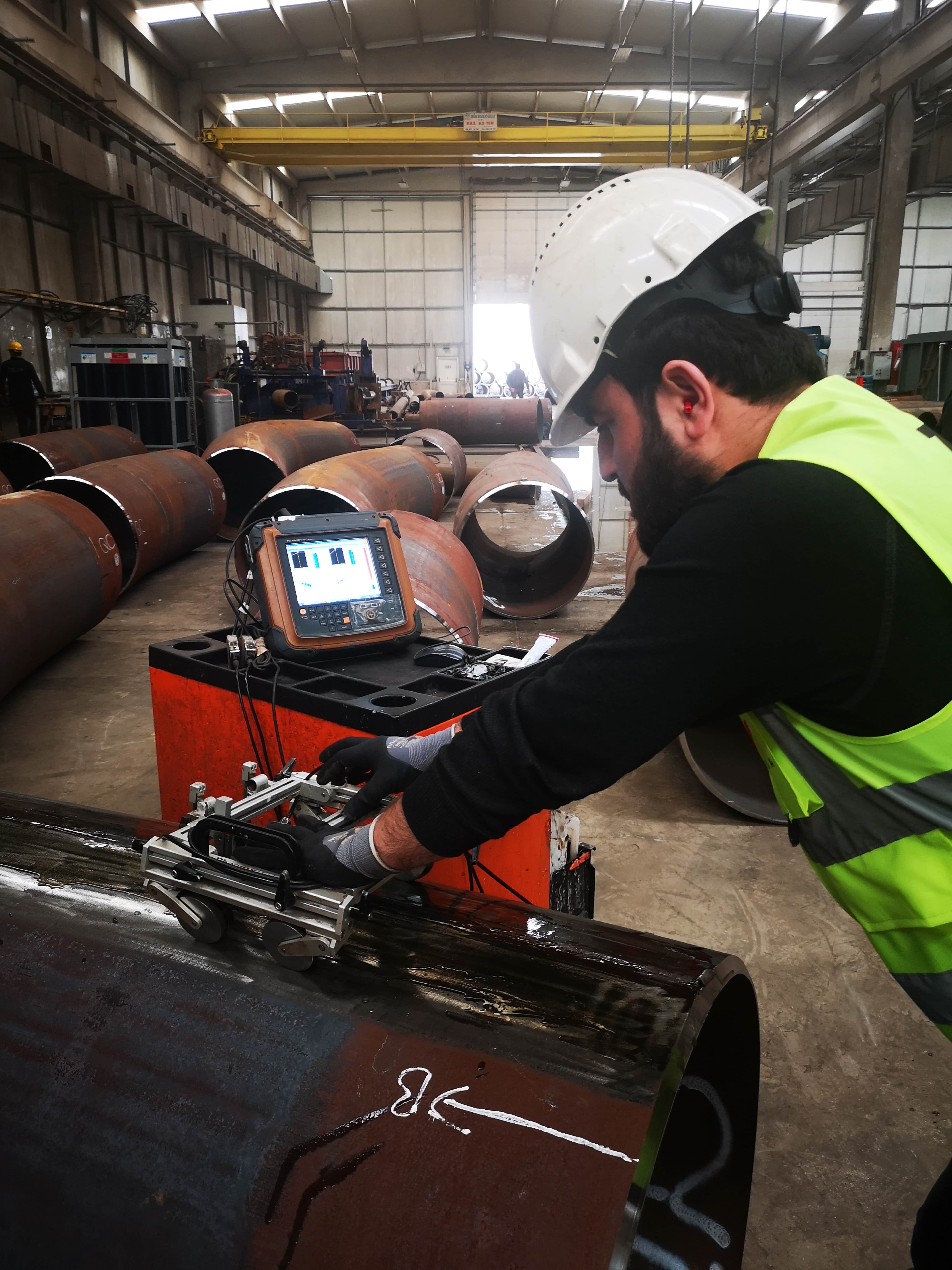
Phased Array Ultrasonic Testing (PAUT) is an advanced ultrasonic inspection method that uses a probe made up of many small piezoelectric elements (typically 16, 32, 64 or 128 elements) instead of a single crystal. Because each element can be excited individually with delay laws (focal laws) in the microsecond range, the resulting sound wave front can be steered to any desired angle in software, focused at a specific depth and swept through the material without physically moving the probe. Controlled shifting of the element firing sequence provides beam steering and focusing, which makes it possible to capture discontinuities of different orientations within a single scan compared with conventional single-element UT.
The fundamental advantage of the method is that the acquired data can be presented in image form. In conventional UT the operator interprets only the A-scan signal, whereas in PAUT these signals are converted into two-dimensional cross-sectional images such as the S-scan (sectorial/angular scan), the E-scan (electronic linear scan) and the C-scan. An S-scan sweeps a range of angles — for example between 40° and 70° — from a single probe position and produces a sectorial map of the weld cross-section; this allows discontinuities oriented at different angles (lack of side-wall fusion, root defects, slag) to be evaluated in the same image. Because the position, depth and size of discontinuities can be read directly from the image, the inspection is understood in a three-dimensional way and the results are stored as archivable records.
In practice a PAUT system comprises a multi-channel instrument, a phased array probe, a wedge that sets the coupling angle of the probe to the material, and usually an encoder. The encoder records the probe position along the scan line and links every data line to a real position, so that flaw length and location are documented correctly along the weld. Focal laws are calculated and verified on calibration blocks according to the thickness and geometry of the part to be inspected and the probe-wedge combination. In sweep mode a wide angular range is covered from a single probe position, which increases inspection speed and optimises the scanning coverage in areas with restricted access.
In weld inspection PAUT is increasingly used as an alternative or complement to radiography; particularly in pipe and pressure vessel welds of greater wall thickness it provides high sensitivity for planar defects such as lack of side-wall fusion, where the fusion direction is critical. When applied together with Time-of-Flight Diffraction (ToFD), the strength of PAUT in detecting near-surface and planar flaws combines with the accuracy of ToFD in flaw height sizing to form a radiography-free inspection strategy (encoded PAUT + ToFD). The method is also used for corrosion mapping, evaluation of cladding/liner disbonding and assessment of volumetric flaws in cast and forged components.
Evaluation and reporting are based on the acceptance criteria defined by the applicable execution standard. Flaw sizing is generally performed on an amplitude basis against reference calibration reflectors (side-drilled holes, notches) or by the diffraction/tip-echo technique using flaw tip signals; the recorded S/C/E-scan images form an integral part of the report and ensure that the inspection remains traceable and repeatable. This traceability and imaged documentation is the main reason PAUT is preferred across a wide range of applications, from manufacturing quality control to periodic inspection and life extension studies. TÜV AUSTRIA SILA KALİTE performs Phased Array inspection with qualified and certified personnel, within the scope of its TS EN ISO/IEC 17020 accreditation and in accordance with the relevant national and international standards.
Method
The inspection begins with a preparation stage in which the weld/material data of the part and the acceptance criteria are established; the inspection surface is cleaned of slag, spatter and rust to achieve a suitable surface roughness, and the probe-wedge and encoder set-up is completed. Focal laws appropriate to the thickness and geometry of the part are then calculated, and angle, distance (TCG/DAC) and sensitivity calibration is verified on a reference calibration block (for example a block with side-drilled holes or notches) to set the system response. During application the probe is moved along the scan line with the encoder, S/E-scan data is collected in real time and coupling continuity is monitored throughout the area. The position, depth and size of discontinuities are evaluated on the acquired images and an accept/reject decision is made according to the acceptance criteria of the execution standard; finally a traceable inspection report is issued containing the S/C/E-scan images, probe-wedge parameters, calibration records and flaw location tables.
Applications
- Manufacturing and periodic inspection of pressure vessel and boiler welds
- Circumferential/longitudinal weld inspection of process and transmission pipelines
- Petrochemical, refinery and power plant equipment
- Storage tank floor and shell welds
- Heavy wall structural steel welds (bridges, offshore, steel structures)
- Volumetric flaw evaluation in cast and forged components
- Corrosion mapping and remaining wall thickness measurement
- Encoded PAUT + ToFD inspection as an alternative to radiography
- Shipyard and shipbuilding weld inspections
Frequently asked questions
Related services
ToFD (Time of Flight Diffraction)
An ultrasonic method that tests weld seams and critical areas with high accuracy, involves no radiation hazard and provides reliable flaw sizing.
TÜRKAK 17020 · AB-0120-MView detailsDigital Radiographic Testing
High-resolution digital radiography with reusable imaging plates, used to detect flaws, cracks, corrosion, erosion and wall thickness loss.
TÜRKAK 17020 · AB-0120-MView detailsCorrosion Mapping
Reliable inspection of pressure vessels, tanks and pipelines through ultrasonic corrosion mapping that covers the entire area instead of localised spot checks.
TÜRKAK 17020 · AB-0120-MView detailsPipeline Inspection with Crawlers
Crawler units that provide fast internal inspection of 16"-60" diameter pipes by producing a panoramic image of the weld seam in a single exposure.
TÜRKAK 17020 · AB-0120-MView detailsGet a quote for your project
Receive a fast, GDPR/KVKK-compliant response for the inspection or certification service you need.